This guide summarizes the functionality of WebAnno from the user’s perspective.
| It is assumed that you plan to test the WebAnno standalone version or an already existing server installation of WebAnno. For information on how to set up WebAnno for a group of users on a server, please refer to the Administrator Guide. |
All materials, including this guide, are available via the WebAnno homepage.
Introduction
Getting started
In order to run WebAnno, you need to have Java installed on your system in version 8 or higher. If you do not have Java installed yet, please the latest Oracle Java or OpenJDK.
Download the stand-alone JAR from the WebAnno downloads page.
Start the application simply by double-clicking on the download JAR file in your file manager. After a moment, a splash screen will be displayed while the application is initializing. Once the initialization is complete, a dialog will appear which you can use to open the application in your default browser or to shut down the application.
Alternatively, you can start it on the command line using
$ java -jar webanno-3.6.5.standalone.jar
The splash screen and dialog will not appear in this case and you have to manually point your browser at http://localhost:8080.
The first time you start the application, a default user with the name admin and the password
admin is created. Use this username and password to log in to the application after opening it
in your browser.
Your first annotation
After logging in, you will see the main menu. Click on Projects to go to the project management page and there click on create to start a new project. Enter a name for your project, select the type annotation project and press save.
Next, switch to the Documents tab and press choose files to select a plain text file from your local harddisk (the file should be in UTF-8 encoding). As part of the import process, WebAnno automatically processes the file to identify sentence and token boundaries.
Use the Home link at the top of the screen to return to the main menu and select Annotation to open your text file in the annotation editor.
To create your first annotation, select Named entity from the Layer dropdown menu on the right side of the screen. Then, use the mouse to select a word in the Annotation area. When you release the mouse button, the annotation is immediately created and you can edit its details in the right sidebar.
Congratulations! You have created your first annotation project.
Where to go from here
To familiarize yourself with the functionalities of WebAnno, try importing some of the WebAnno downloads page[example projects].
Running WebAnno in the way you just did is a great way to get started and try out its capabilities, but it is not the best way of working with the application. If you like WebAnno, please be sure to check out the Administrator Guide to learn how to set up a production-ready instance.
|
By default, WebAnno creates and uses an embedded database and stores all its data in folder called |
|
By default the server starts on port 8080 and you can access it via a browser at |
Workflow
The following image shows an exemplary workflow of an annotation project with WebAnno.
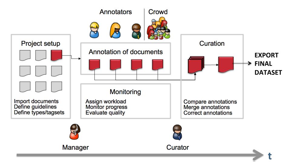
First, the projects need to be set up. In more detail, this means that users are to be added, guidelines need to be provided, documents have to be uploaded, tagsets need to be defined and uploaded, etc. The process of setting up and managing a project are explicitly described in Projects.
After the setup of a project, the users who were assigned with the task of annotation annotate the documents according to the guidelines. The task of annotation is further explained in Annotation. The work of the annotators is managed and controlled by monitoring. Here, the person in charge has to assign the workload. For example, in order to prevent redundant annotation, documents which are already annotated by several other annotators and need not be annotated by another person, can be blocked for others. The person in charge is also able to follow the progress of individual annotators. All these tasks are demonstrated in Monitoring in more detail. The person in charge should not only control the quantity, but also the quality of annotation by looking closer into the annotations of individual annotators. This can be done by logging in with the credentials of the annotators.
After at least two annotators have finished the annotation of the same document by clicking on Done, the curator can start his work. The curator compares the annotations and corrects them if needed. This task is further explained in Curation.
The document merged by the curator can be exported as soon as the curator clicked on Done for the document. The extraction of curated documents is also explained in Projects.
Core functionalities
Logging in
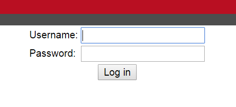
Upon opening the application in the browser, the login screen opens. Please enter your credentials to proceed.
| When WebAnno is started for the first time, a default user called admin with the password admin is automatically created. Be sure to change the password for this user after logging in (see User Management). |
Menu bar
At the top of the screen, there is always a menu bar visible which allows a quick navigation within the application. It offers the following items:
-
Home - always takes you back to the main menu.
-
Help - opens the integrated help system in a new browser window.
-
Username - shows the name of the user currently logged in. If the administrator has allowed it, this is a link which allows accessing the current user’s profile, e.g. to change the password.
-
Log out - logs out of the application.
-
Timer - shows the remaining time until the current session times out. When this happens, the browser is automatically redirected to the login page.
Main Menu
After login, you will be presented with the overview screen. This screen can be reached at any time from within the GUI by clicking on the Home link in the left upper corner.
Here, you can navigate to one of the currently seven options:
-
Annotation - The page to perform annotations
-
Curation - Compare and merge annotations from multiple users (only for curators)
-
Correction - Correcting automatic annotation (under development)
-
Automation - Creating automatically annotated data
-
Projects - Set up or change annotation projects (only for administrators and managers)
-
Monitoring - Allows you to see the projects, their progress and change document status (only for managers and curators)
-
User Management - Allows you to manage the rights of users
Please click on the functionality you need. The individual functionalities will be explained in further chapters.
Annotation
| This functionality is only available to annotators and managers. Annotators and managers only see projects in which they hold the respective roles. |
The annotation screen allows to view text documents and to annotate them.
Opening a Document
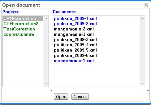
When navigating to the Annotation page, a dialogue opens that allows you to select a project, and a document within the project. If you want to open a different project or document later, click on Open to open the dialog.
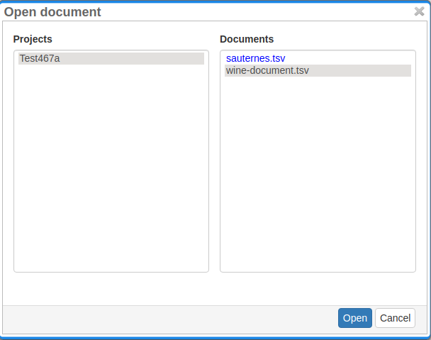
Projects appear as folders, and contain the documents of the project. Double-click on a document to open it for annotation. Document names written in black show that the document has not been opened by the current user, blue font means that it has already been opened, whereas red font indicates that the document has already been marked as done.
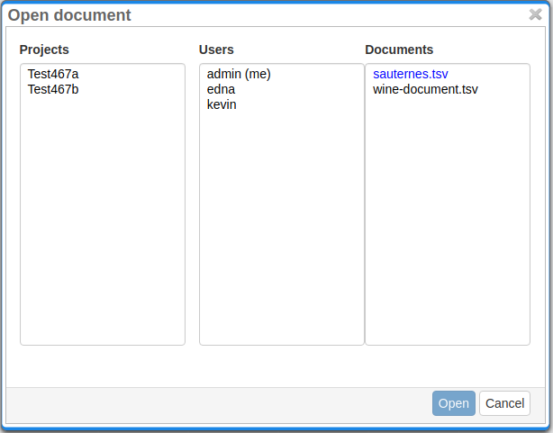
Users that are managers can additionally open other users' documents to view their annotations but cannot change them. This is done by selecting the project, user and then document in the described dialogue. The user’s own name is listed at the top and marked (me).
Navigation
Sentence numbers on the left side of the annotation page show the exact sentence numbers in the document.
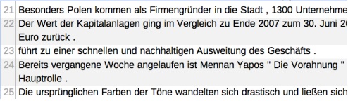
The arrow buttons first page, next page, previous page, last page, and go to page allow you to navigate accordingly. The Prev. and Next buttons in the Document frame allow you to go to the previous or next document on your project list. You can also use the following keyboard assignments in order to navigate only using your keyboard.
| Key | Action |
|---|---|
HOME |
jump to first sentence |
END |
jump to last sentence |
PAGE DOWN |
move to the next page, if not in the last page already |
PAGE UP |
move to previous page, if not already in the first page |
SHIFT+PAGE DOWN |
go to next document in project, if available |
SHIFT+PAGE UP |
go to previous document in project, if available |
A click on the Help button displays the Guidelines for the tool and The Annotator’s Guide to NER-Annotation. When you are finished with annotating or curating a document, please click on the Done button, so that the document may be further processed. If the button above the Done is a cross symbol, it means the documents have already been finished. If the symbol has a tick, it is still open.
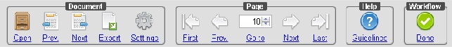
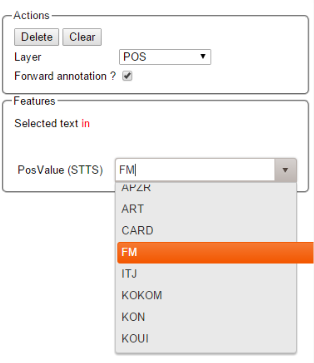
Annotation of spans works by selecting the span, or double-clicking on a word. This activates the Actions-box on the right, where you can choose a layer. One can also type in the initial letters and chose the needed layer. After having chosen a layer, the drop-down menu inside the Features-box displays the features you can use during the annotation. The tag can be selected out of the drop-down menu inside the Features-box which contains the tags of the chosen layer.
To change or delete an annotation, double-click on the annotation (span or link annotations). The Actions-box is now activated. Changes and Deletions are possible via the respective buttons.
Link annotations (between POS tags) are created by selecting the starting POS-tag, then dragging the arrow to connect it to its target POS tag. All possible targets are highlighted.

Creating annotations
The Layer box in the right sidebar shows the presently active layer span layer. To create a span annotation, select a span of text or double click on a word.
If a relation layer is defined on top of a span layer, clicking on a corresponding span annotation and dragging the mouse creates a relation annotation.
Once an annotation has been created or if an annotation is selected, the Annotation box shows the features of the annotation.
The result of changing the active layer in the Layer box while an annotation is selected depends on the Remember layer setting. If this setting is disabled, changing the active layer causes the currently selected annotation to be deleted and replaced with an annotation of the selected layer. In this mode, it is necessary to unselect the current annotation by pressing the Clear button before an annotation on another layer can be created. If Remember layer is enabled, changing the active layer has no effect on the currently selected annotation.
The definition of layers is covered in Section Layers.
Spans
To create an annotation over a span of text, click with the mouse on the text and drag the mouse to create a selection. When you release the mouse, the selected span is activated and highlighted in orange. The annotation detail editor is updated to display the text you have currently selected and to offer a choice on which layer the annotation is to be created. As soon as a layer has been selected, it is automatically assigned to the selected span. To delete an annotation, select a span and click on Delete. To deactivate a selected span, click on Clear.
Depending on the layer behavior configuration, span annotations can have any length, can overlap, can stack, can nest, and can cross sentence boundaries.
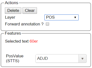
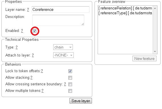
For example, for NE annotation, select the options as shown below (red check mark):
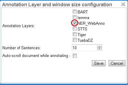
NE annotation can be chosen from a tagset and can span over several tokens within one sentence. Nested NE annotations are also possible (in the example below: "Frankfurter" in "Frankfurter FC").

Lemma annotation, as shown below, is freely selectable over a single token.

POS can be chosen over one token out of a tagset.

To create a zero-length annotation, hold SHIFT and click on the position where you wish to create the annotation. To avoid accidental creations of zero-length annotations, a simple single-click triggers no action by default. The lock to token behavior cancels the ability to create zero-length annotations.
A zero-width span between two tokens that are directly adjacent, e.g. the full stop at the
end of a sentence and the token before it (end.) is always considered to be at the end of the
first token rather than at the beginning of the next token. So an annotation between d and .
in this example would be rendered at the right side of end rather than at the left side of ..
|
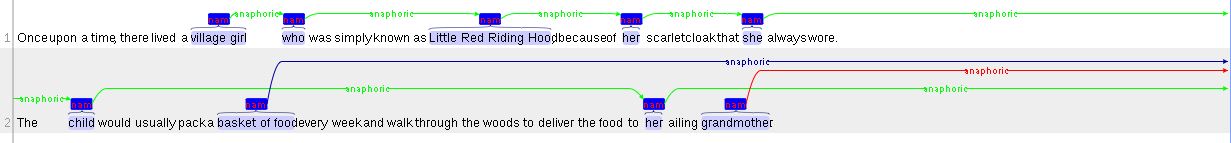
Co-reference annotation can be made over several tokens within one sentence. A single token sequence can have several co-ref spans simultaneously.
Forward annotation mode
The forward annotation mode is useful for annotation tasks where every single token should be receiving an annotation - typical examples are part-of-speech of lemma annotation. When this mode is enabled, completing an annotation automatically creates another annotation on the next token.
The forward annotation mode is available for layers fulfilling the following conditions:
-
the layer is a span layer
-
the layer anchors to single tokens
-
there is exactly one enabled and visible String feature
-
if the feature uses a tagset, this tagset must be non-empty
If the feature is associated with a tagset, you will notice that the cursor does not jump to the
feature editor when an annotation is created. This is intentional. Assume your tagset includes the
tags ADJ, ADV and NOUN. When you press the A key once, the feature editor loads the first
value starting with that letter, i.e. ADJ. Press A again to move to the second tag ADV.
Pressing a key multiple times cycles through all the tags starting with the respective letter. Thus,
pressing A a third time loads ADJ again. Pressing N loads NOUN.
If the feature is associated with a tagset, pressing the BACKSPACE key deletes the current annotation and moves on. Otherwise the current annotation is removed if the feature editor is empty (no value entered) when completing the annotation.
Press ENTER to complete the annotation and to move on to the next token. In the general case, a new annotation is created on the next token and it is loaded into the feature editor. However, if it is not permitted to stack annotations or make them overlap (i.e. if the value of the behaviour setting for Overlap is set to anything else than Any) and if there is already an annotation on that token, this would naturally fail. In this case, no new annotation is created and instead an existing annotation is opened for editing.
If the Remember layer setting is turned on, it is possible to select and edit an annotation which is not on the layer for which the forward-mode is enabled. In this case, the forward-mode is paused and the user can edit the annotation normally. The forward-mode resumes when the user creates a new annotation or selects an annotation on the forward-enabled layer.
Relations
To create a relation annotation, click on a span annotation and drag the mouse to another span annotation. While you drag, an arc is drawn. It is not possible to create arbitrary relation annotations. In order to create one, a corresponding relation layer needs to be defined between the source and target spans.
Depending on the layer behavior configuration, relation annotations can stack, can cross each other, and can cross sentence boundaries.
To create a relation from a span to itself, press the SHIFT key before starting to drag the mouse and hold it until you release the mouse button.
To abort the creation of an annotation, hold the CTRL key when you release the mouse button.
| Currently, there can be at most one relation layer per span layer. Relations between spans of different layers are not supported. |
| Not all arcs displayed in the annotation view are belonging to chain or relation layers. Some are induced by Link Features. |
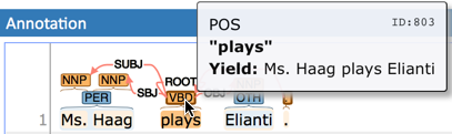
When moving the mouse over an annotation with outgoing relations, the info popup includes the yield of the relations. This is the text transitively covered by the outgoing relations. This is useful e.g. in order to see all text governed the head of a particular dependency relation. The text may be abbreviated.
Chains
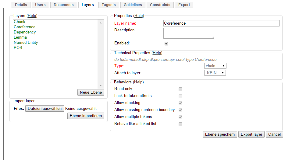
A chain layer includes both, span and relation annotations, into a single structural layer. Creating a span annotation in a chain layer basically creates a chain of length one. Creating a relation between two chain elements has different effects depending on whether the linked list behavior is enabled for the chain layer or not. To enable or disable the linked list behaviour, go to Layers in the Projects Settings mode. After choosing Coreference, linked list behaviour is displayed in the checkbox and can either be marked or unmarked.
To abort the creation of an annotation, hold CTRL when you release the mouse button.
| Linked List | Condition | Result |
|---|---|---|
disabled |
the two spans are already in the same chain |
nothing happens |
disabled |
the two spans are in different chains |
the two chains are merged |
enabled |
the two spans are already in the same chains |
the chain will be re-linked such that a chain link points from the source to the target span, potentially creating new chains in the process. |
enabled |
the two spans are in different chains |
the chains will be re-linked such that a chain link points from the source to the target span, merging the two chains and potentially creating new chains from the remaining prefix and suffix of the original chains. |
Primitive Features
Supported primitive features types are string, boolean, integer, and float. Boolean features are displayed as a checkbox that can either be marked or unmarked. Integer and float features are displayed using a number field. String features are displayed using a text field or - in case they have a tagset - using a combobox.
Link Features
Link features can be used to link one annotation to others. Before a link can be made, a slot with a role must be added. Enter the role label in the text field and press the add button to create the slot. Next, click on field in the newly created slot to arm it. The field’s color will change to indicate that it is armed. Now you can fill the slot by double-clicking on a span annotation. To remove a slot, arm it and then press the del button.
Settings
Once the document is opened, a default of 5 sentences is loaded on the annotation page. The Settings button will allow you to specify the settings of the annotation layer.
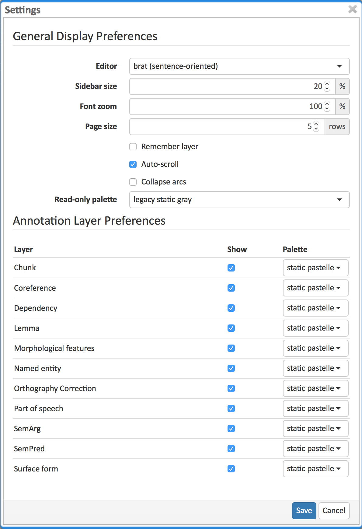
The Editor setting can be used to switch between different modes of presentation. It is currently only available on the annotation page.
The Sidebar size controls the width of the sidebar containing the annotation detail edtior and actions box. In particular on small screens, increasing this can be useful. The sidebar can be configured to take between 10% and 50% of the screen.
The Font zoom setting controls the font size in the annotation area. This setting may not apply to all editors.
The Page size controls how many sentences are visible in the annotation area. The more sentences are visible, the slower the user interface will react. This setting may not apply to all editors.
The Remember layer checkbox controls if the annotation layer selected in the Actions box. It will work as main layer during the annotation process. Only instances of this layer will be created, even if an annotation in another layer is selected. If necessary, it is possible to change active instances. Still, if a new instance is selected, the main layer is automatically activated.
The Auto-scroll setting controls if the annotation view is centered on the sentence in which the last annotation was made. This can be useful to avoid manual navigation. This setting may not apply to all editors.
The Collaps arcs setting controls whether long ranging relations can be collapsed to save space on screen. This setting may not apply to all editors.
The Read-only palette controls the coloring of annotations on read-only layers. This setting overrides any per-layer preferences.
Layer preferences
In this section you can select which annotation layers are displayed during annotation and how they are displayed.
Hiding layers is useful to reduce clutter if there are many annotation layers. Mind that hiding a layer which has relations attached to it will also hide the respective relations. E.g. if you disable POS, then no dependency relations will be visible anymore.
The Palette setting for each layer controls how the layer is colored. There are the following options:
-
static / static pastelle - all annotations receive the same color
-
dynamic / dynamic pastelle - all annotations with the same label receive the same color. Note that this does not imply that annotations with different labels receive different colors.
-
static grey - all annotations are grey.
Mind that there is a limited number of colors such that eventually colors will be reused. Annotations on chain layers always receive one color per chain.
Export
Annotations are always immediately persistent in the backend database. Thus, it is not necessary to save the annotations explicitly. Also, losing the connection through network issues or timeouts does not cause data loss. To obtain a local copy of the current document, click on export button. The following frame will appear:
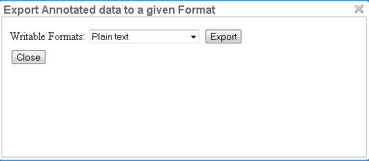
Choose your preferred format. Please take note of the facts that the plain text format does not contain any annotations and that the files in the binary format need to be unpacked before further usage. For further information the supported formats, please consult the corresponding chapter Formats.
The document will be saved to your local disk, and can be re-imported via adding the document to a project by a project manager. Please export your data periodically, at least when finishing a document or not continuing annotations for an extended period of time.
Curation
| This functionality is only available to curators. |
When navigating to the Curation Page, the procedure for opening projects and documents is the same as in Annotation. The navigation within the document is also equivalent to Annotation.
No curatable documents |
Red |
Curatable documents |
Green |
New |
Black |
Annotation in progress |
Black |
Curation in progress |
Blue |
Curation finished |
Red |
In the left frame of the window, named Sentences, an overview of the chosen document is displayed. Sentences are represented by their number inside the document. Sentences containing a disagreement between annotators are colored in red. Click on a sentence in order to select it and to to edit it in the central part of the page.
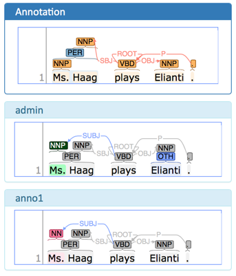
The center part of the annotation page is divided into the Annotation pane which is a full-scale annotation editor and contains the final data from the curation step. Below it are multiple read-only panes containing the annotations from individual annotators. Clicking on an annotation in any of the annotator’s panes transfers the respective annotation to the Annotation pane.
When a document is opened for the first time in the curation page, the application analyzes agreements and disagreemens between annotators. All annotations on which all annotators agree are automatically copied to the Annotation pane. Any annotations on which the annotators disagree are skipped.
The annotator’s panes are color-coded according to their relation with the contents of the Annotation pane and according to the agreement status. If the annotations were the same, they are marked grey in the lower panels. If the annotators do not agree, the respective annotations are show in dark blue in the lower panels. By default, they are not taken into the merged file (cf. Merging strategies).
Left-click on an annotation in one of the lower panels to merge it. This action copies the annotation to the upper panel. The merged annotation will turn green in the lower panel from which it was selected. If other annotators had a conflicting opinion, these will turn red in the lower panels of the respective annotators.
Right-click on an annotation in the lower panels to bring up a menu with additional options.
-
Merge all XXX: merge all annotations of the given type from the selected annotator. Note that this overrides any annotations of the type which may previously have been merged or manually created in the upper panel.
| The upper Annotation pane is not color-coded. It uses whatever coloring strategy is configured in the Settings dialog. |
Grey |
all annotators agree |
Blue |
disagreement requiring curation; annotators disagree and there is no corresponding annotation in the upper Annotation pane yet |
Green |
accepted; matches the corresponding annotation in the upper Annotation pane |
Red |
rejected; different to the corresponding annotation in the upper Annotation pane |
Merging strategies
By default, the merging strategy only considers annotations if all annotators made the same annotation at the same location (i.e. complete and agreeing annotations) - i.e. it considers any annotations not provided by all annotators as a disagreement between the annotators.
However, there are situations where it is desirable to merge annotations from all annotators, even if some did not provide it. For example, if your project has two annotators, one working on POS tagging and another working on lemmatization, then as a curator, you might simply want to merge the annotators from the two. This can be done by using the Re-merge action and activating the checkbox Merge incomplete annotations. This will re-merge the current document (i.e. discard the entire state of curation and merge from scratch).
Anonymized curation
By default, the curator can see the annotators names on the curation page. However, in some cases, it may not be desirable for the curator to see the names. In this case, enable the option Anonymous curation in the project detail settings. Users with the curator role will then only see an anonymous label like Anonymized annotator 1 instead of the annotator names. Users who are project managers can still see the annotator names.
| The order of the annotators is not randomized - only the names are removed from the UI. Only annotators who have marked their documents as finished are shown. Thus, which annotator recieves which number may changed depending on documents being marked as finished or put back into progress. |
Monitoring
| This functionality is only available to curators and * managers*. |
This page allows to observe the progress and document status of projects you are responsible for. Moreover, you are able to see the time of the last login of every user and observe the agreement between the annotators. After clicking on Monitoring in the main menu, the following page is displayed:
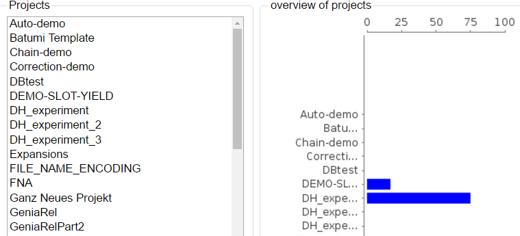
In the right frame, the overall progress of all projects is displayed. In the left frame one sees all projects that you are allowed to curate. By clicking on one of the projects on the left, it may be selected and the following view is opened:
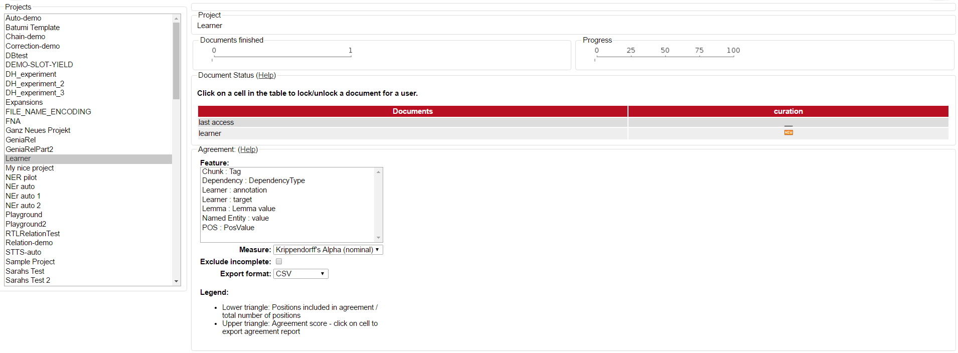
The percentual progress out of the workload for individual annotators may be viewed as well as the number of finished documents.
Below the document overview, a measuring for the inter-annotator-agreement can be selected by opening the Measure dropdown menu. Three different units of measurement are possible: Cohen’s kappa as implemented in DKPro Statistics, Fleiss' kappa and Krippendorff’s alpha. Below the Measure dropdown menu, an export format can be chosen. Currently, only CSV format is possible.
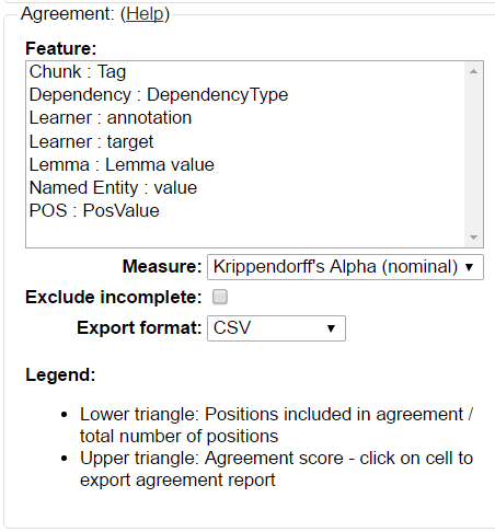
Above the Measure dropdown menu, the Feature box allows the selection of layers for which an agreement shall be computed. Double-clicking on a layer starts the computation of the agreement and an outline is shown to the left side of the box:

The following table explains the different symbols which explain the status of a document for a user and the described task.
| Symbol | Meaning |
|---|---|
|
Annotation has not started yet |
|
Document not available to user |
|
Annotation is in progress |
|
Annotation is complete |
|
Curation is in progress |
You can also alter the document status of annotators. By clicking on the symbols you can change between Done and In Progress. You can also alter between New and Locked status. The second column of the document status frame displays the status of the curation.
As there is only one curator for one document, curation is not divided into individual curators.
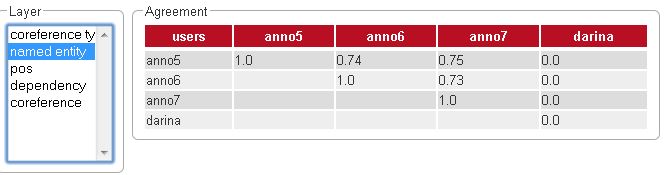
Scrolling down, two further frames become visible. The left one, named Layer, allows you to chose a layer in which pairwise kappa agreement between annotators will be calculated.
Agreement
Agreement can be inspected on a per-feature basis and is calculated pair-wise between all annotators across all documents.
The first time a feature is selected for agreement inspection, it takes a moment to calculate the differences between the annotated documents. Switching between different features subsequently is much faster.
Agreement is calculated in two steps:
-
Generation of positions and configuration sets - all documents are scanned for annotations and annotations located at the same positions are collected in configuration sets. To determine if two annotations are at the same position, different approaches are used depending on the layer type. For a span layer, the begin and end offsets are used. For a relation layer, the begin and end offsets of the source and target annotation are used. Chains are currently not supported.
-
Calculation of pairwise agreement - based on the generated configuration sets, agreement is calculated. There are two cases where a configuration set may be omitted from the pairwise agreement calculation:
-
one of the users did not make an annotation at the position;
-
one or both of the users did not assign a value to the feature on which agreement is calculated at the position.
-
The lower part of the agreement matrix displays how many configuration sets were used to calculate agreement and how many were found in total. The upper part of the agreement matrix displays the pairwise Cohen’s kappa scores.
The agreement calculations considers an unset feature (with a null value) to be equivalent to a
feature with the value of an empty string. Empty strings are considered valid labels and are not
excluded from agreement calculation.
Annotations for a given position are considered complete when both annotators have made an
annotation. Unless the agreement measure supports null values (i.e. missing annotations),
incomplete annotations are implicitly excluded from the agreement calculation. If the agreement
measure does support incomplete annotations, then excluding them or not is the users' choice.
| Feature value annotator 1 | Feature value annotator 2 | Agreement | Complete |
|---|---|---|---|
|
|
yes |
yes |
|
|
no |
yes |
no annotation |
|
no |
no |
empty |
|
no |
yes |
empty |
empty |
yes |
yes |
null |
empty |
yes |
yes |
empty |
no annotation |
no |
no |
| Multiple interpretations in the form of stacked annotations are not supported in the agreement calculation! This also includes relations for which source or targets spans are stacked. |
Projects
| This functionality is only available to managers of existing projects, project creators (users with the ability to create new projects), and administrators. Project managers only see projects in which they hold the respective roles. Project creators only see projects in which they hold the project manager role. |
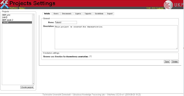
This is the place to specify/edit annotation projects. You can either select one of the existing projects for editing, or click Create Project to add a project.
Although correction and automation projects function similarly, the management differs after the creation of the document. For further description, look at the corresponding chapters Automation and Correction.
Click on Create Project to create a new project.
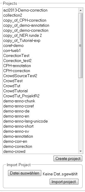
After doing so, a new pane is displayed, where you can name and describe your new project. It is also important to chose the kind of project you want to create. You have the choice between annotation, automation, and correction. Please do not forget to save.
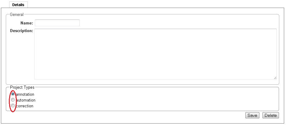
After saving the details of the new project, it can be treated like any other already existing one. Also, a new pane with many options to organize the project is displayed.
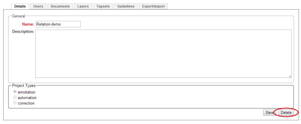
To delete a project, click on it in the frame Details. The project details are displayed. Now, click on Delete.
The pane with the options to organize and edit a project, as described above, can also be reached by clicking on the desired project in the left frame.
By clicking on the tabs, you can now set up the chosen project.
Import
Here, you can import project archives such as the example projects provided on our website or projects exported from the Export tab.
When a user with the role project creator imports a project, that user automatically becomes a manager of the imported project. However, no permissions for the project are imported!
| If the current instance has users with the same name as those who originally worked on the import project, the manager can add these users to the project and they can access their annotations. Otherwise, only the imported source documents are accessible. |
When a user with the role administrator imports a project, the user can choose whether to import the permissions and whether to automatically create users who have permissions on the imported project but so far do not exist. If this option to create missing users disabled, but the option to import permissions is enabled, then projects still maintain their association to users by name. If the respective user accounts are created manually after the import, the users will start showing up in the projects.
| Automatically added users are disabled and have no password. They must be explicitly enabled and a password must be set before the users can log in. |
Users
After clicking on the Users tab, you are displayed with a new pane in which you can add new users by clicking on the Add users text field. You get a dropdown list of enabled users in the system which can be added to the project. Any users which are already part of the project are not offered. As you type the dropdown list with the users is filtered to match your input. By clicking on a username or by pressing enter you can select the corresponding user. You can keep typing to add more users to the project. When you press the Add button the selected users are added to your project.
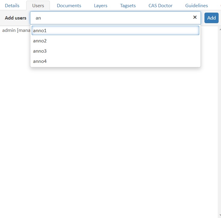
| For privacy reasons, the administrator may choose to restrict the users shown in the dropdown. If this is the case, you have to enter the full name of a user before it appears in the dropdown and can be added. |
By default, the users are added to the project as annotators. If you want to assign additional roles, you can do so by clicking on the user and then on Permissions pane select the appropriate permissions.
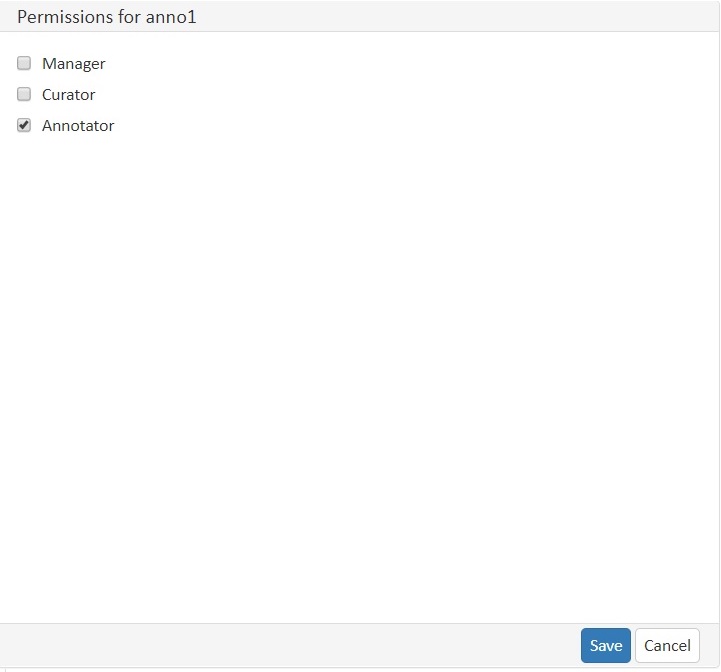
After ticking the wished permissions, click on Save. To remove a user, remove all the permissions and then click on Save.
Documents
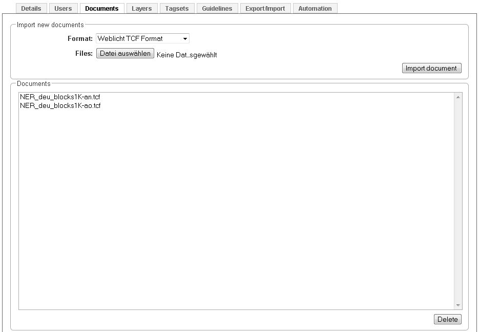
To add or delete documents, you have to click on the tab Documents in the project pane. Two frames will be displayed. In the first frame you can import new documents.
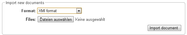
Choose a document by clicking on Choose Files. Please mind the format, which you have to choose above. Then click on Import Document. The imported documents can be seen in the frame below. To delete a document from the project, you have to click on it and then click on Delete in the right lower corner.
Layers
All annotations belong to an annotation layer. Each layer has a structural type that defines if it is a span, a relation, or a chain. It also defines how the annotations behave and what kind of features it carries.
Creating a custom layer
This section provides a short walk-through on the creation of a custom layer. The following sections act as reference documentation providing additional details on each step. In the following example, we will create a custom layer called Sentiment with a feature called Polarity that can be negative, neutral, or positive.
-
Create the layer Sentiment
-
Go to the Layers tab in your project’s settings and press the Create layer button
-
Enter the name of the layer in Layer name: Sentiment
-
Choose the type of the layer: Span
-
Enable Allow multiple tokens because we want to mark sentiments on spans longer than a single token.
-
Press the Save layer button
-
-
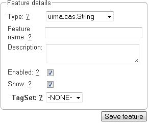
Create the feature Polarity
-
Press the New feature button
-
Choose the type of the feature: uima.cas.String
-
Enter the name of the feature: Polarity
-
Press Save feature
-
-
Create the tagset Polarity values
-
Go to the Tagsets tab and press Create tagset
-
Enter the name of the tagset: Polarity values
-
Press Save tagset
-
Press Create tag, enter the name of the tag: negative, press Save tag
-
Repeat for neutra and positive
-
-
Assign the tagset Polarity values to the feature Polarity
-
Back in the Layers tab, select the layer: Sentiment and select the feature: Polarity
-
Set the tagset to Polarity values
-
Press Save feature
-
Now you have created your first custom layer.
Built-in layers
WebAnno comes with a set of built-in layers that allow you to start annotating immediately. Also, many import/export formats only work with these layers as their semantics are known. For this reason, the ability to customize the behaviors of built-in layers is limited and it is not possible to extend them with custom features.
| Layer | Type | Enforced behaviors |
|---|---|---|
Chunk |
Span |
Lock to multiple tokens,
no overlap,
no sentence boundary crossing |
Coreference |
Chain |
(no enforced behaviors) |
Dependency |
Relation over POS, |
Any overlap,
no sentence boundary crossing |
Lemma |
Span |
Locked to token offsets,
no overlap,
no sentence boundary crossing |
Named Entity |
Span |
(no enforced behaviors) |
Part of Speech (POS) |
Span |
Locked to token offsets,
no overlap,
no sentence boundary crossing |
The coloring of the layers signal the following:
| Color | Description |
|---|---|
green |
built-in annotation layer, enabled |
blue |
custom annotation layer, enabled |
red |
disabled annotation layer |
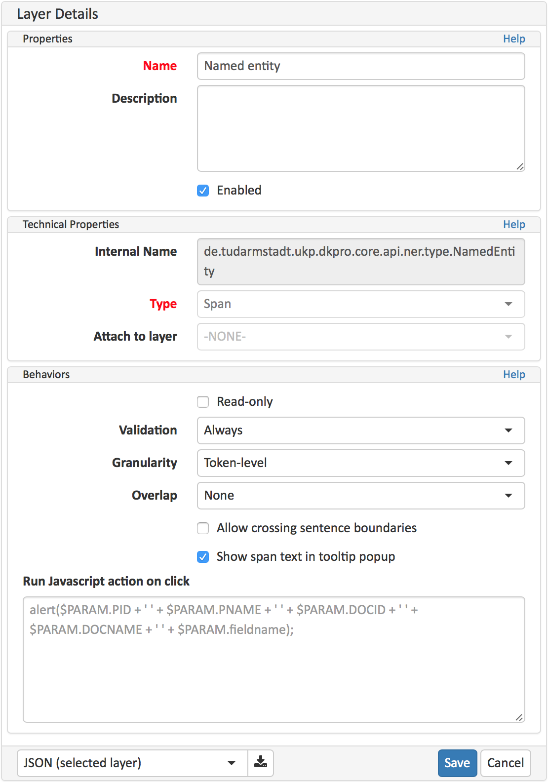
To create a custom layer, select Create Layer in the Layers frame. Then, the following frame will be displayed.
At times, it is useful to export the configuration of a layer or of all layers, e.g. to copy them to another project. There are two options:
-
JSON (selected layer): exports the currently selected layer as JSON. If the layer depends on other layers, these are included as well in the JSON export.
-
UIMA (all layers): exports a UIMA type system description containing all layers of the project. This includes built-in types (i.e. DKPro Core types) and it may include additional types required to allow loading the type system description file again. However, this type system description is usually not sufficient to interpret XMI files produced by WebAnno. Be sure to load XMI files together with the type system description file which was included in the XMI export.
Both types of files can be imported back into WebAnno. Note that any built-in types that have have been included in the files are ignored on import.
Properties
| Property | Description |
|---|---|
Layer name |
The name of the layer (obligatory) |
Description |
A description of the layer. This information will be shown in a tooltip when the mouse hovers over the layer name in the annotation detail editor panel. |
Enabled |
Whether the layer is enabled or not. Layers can currently not be deleted, but they can be disabled. |
| When a layer is first created, only ASCII characters are allowed for the layer name because the internal UIMA type name is derived from the initial layer name. After the layer has been created, the name can be changed arbitrarily. The internal UIMA type name will not be updated. The internal UIMA name is e.g. used when exporting data or in constraint rules. |
Technical Properties
In the frame Technical Properties, the user may select the type of annation that will be made with this layer: span, relation, or chain.
| Property | Description |
|---|---|
Internal name |
Internal UIMA type name |
Type |
The type of the layer (obligatory, see below) |
Attach to layer
(Relations) |
Determines which span layer a relation attaches to. Relations can only be created between annotations of this span layer. |
The layer type defines the structure of the layer. Three different types are supported: spans, relations, and chains.
| Type | Description | Example |
|---|---|---|
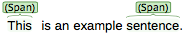
Span |
Continous segment of text delimited by a start and end character offset. The example shows two spans. |
|
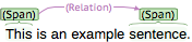
Relation |
Binary relation between two spans visualized as an arc between spans. The example shows a relation between two spans. |
|
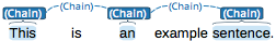
Chain |
Directed sequence of connected spans in which each span connects to the following one. The example shows a single chain consisting of three connected spans. |
|
For relation annotations the type of the spans which are to be connected can be chosen in the field Attach to layer. Here, only non-default layers are displayed. To create a relation, first the span annotation needs to be created.
| Currently for each span layer there can be at most one relation layer attaching to it. |
| It is currently not possible to create relations between spans in different layers. For example if you define span layers called Men and Women, it is impossible to define a relation layer Married to between the two. To work around this limitation, create a single span layer Person with a feature Gender instead. You can now set the feature Gender to Man or Woman and eventually define a relation layer Married to attaching to the Person layer. |
Behaviours
| Behavior | Description |
|---|---|
Read-only |
The layer may be viewed but not edited. |
Validation |
When pre-annotated data is imported or when the behaviors settings are changed, it is possible that annotations exist which are not conforming to the current behavior settings. This setting controls when a validation of annotations is performed. Possible settings are Never (no validation when a user marks a document as finished) and Always (validation is performed when a user marks a document as finished). Mind that changing the document state via the Monitoring page does not trigger a validation. Also, problematic annotations are highlighted using an error marker in the annotation interface. NOTE: the default setting for new projects/layers is Always, but for any existing projects or for projects imported from versions of WebAnno where this setting did not exist yet, the setting is initialized with Never. |
Granularity
(span, chain) |
The granularity controls at which level annotations can be created. When set to Character-level, annotations can be created anywhere. Zero-width annotations are permitted. When set to Token-level or Sentence-level annotation boundaries are forced to coincide with token/sentence boundaries. If the selection is smaller, the annotation is expanded to the next larger token/sentence covering the selection. Again, zero-width annotations are permitted. When set to Single tokens only may be applied only to a single token. If the selection covers multiple tokens, the annotation is reduced to the first covered token at a time. Zero-width annotations are not permitted in this mode. Note that in order for the Sentence-level mode to allow annotating multiple sentences, the Allow crossing sentence boundary setting must be enabled, otherwise only individual sentences can be annotated. |
Overlap |
This setting controls if and how annotations may overlap. For span layers, overlap is defined in terms of the span offsets. If any character offset that is part of span A is also part of span B, then they are considered to be overlapping. If two spans have exactly the same offsets, then they are considered to be stacking. For relation layers, overlap is defined in terms of the end points of the relation. If two relations share any end point (source or target), they are considered to be overlapping. If two relations have exactly the same end points, they are considered to be stacking. Note that some export formats are unable to deal with stacked or overlapping annotations. E.g. the CoNLL formats cannot deal with overlapping or stacked named entities. |
Allow crossing sentence boundary
(chain) |
Allow annotations to cross sentence boundaries. |
Behave like a linked list |
Controls what happens when two chains are connected with each other. If this option is disabled, then the two entire chains will be merged into one large chain. Links between spans will be changed so that each span connects to the closest following span - no arc labels are displayed. If this option is enabled, then the chains will be split if necessary at the source and target points, reconnecting the spans such that exactly the newly created connection is made - arc labels are available. |
Features
In this section, features and their properties can be configured.
| When a feature is first created, only ASCII characters are allowed for the feature name because the internal UIMA name is derived from the initial layer name. After the feature has been created, the name can be changed arbitrarily. The internal UIMA feature name will not be updated. The internal UIMA name is e.g. used when exporting data or in constraint rules. |
| Property | Description |
|---|---|
Internal name |
Internal UIMA feature name |
Type |
The type of the feature (obligatory, see below) |
Name |
The name of the feature (obligatory) |
Description |
A description that is shown when the mouse hovers over the feature name in the annotation detail editor panel. |
Enabled |
Features cannot be deleted, but they can be disabled |
Show |
Whether the feature value is shown in the annotation label. If this is disabled, the feature is only visible in the annotation detail editor panel. |
Remember |
Whether the annotation detail editor should carry values of this feature over when creating a new annotation of the same type. This can be useful when creating many annotations of the same type in a row. |
Tagset
(String) |
The tagset controlling the possible values for a string feature. |
The following feature types are supported.
| Type | Description |
|---|---|
uima.cas.String |
Textual feature that can optionally be controlled by a tagset. It is rendered as a text field or as a combobox if a tagset is defined. |
uima.cas.Boolean |
Boolean feature that can be true or false and is rendered as a checkbox. |
uima.cas.Integer |
Numeric feature for integer numbers. |
uima.cas.Float |
Numeric feature for decimal numbers. |
uima.tcas.Annotation
(Span layers) |
Link feature that can point to any arbitrary span annotation |
other span layers
(Span layers) |
Link feature that can point only to the selected span layer. |
| Please take care that when working with non-custom layers, they have to be ex- and imported, if you want to use the resulting files in e.g. correction projects. |
Tagsets
To manager the tagsets, click on the tab Tagsets in the project pane.
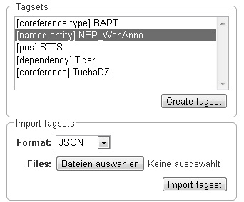
To edit one of the existing tagsets, select it by a click. Then, the tagset characteristics are displayed.
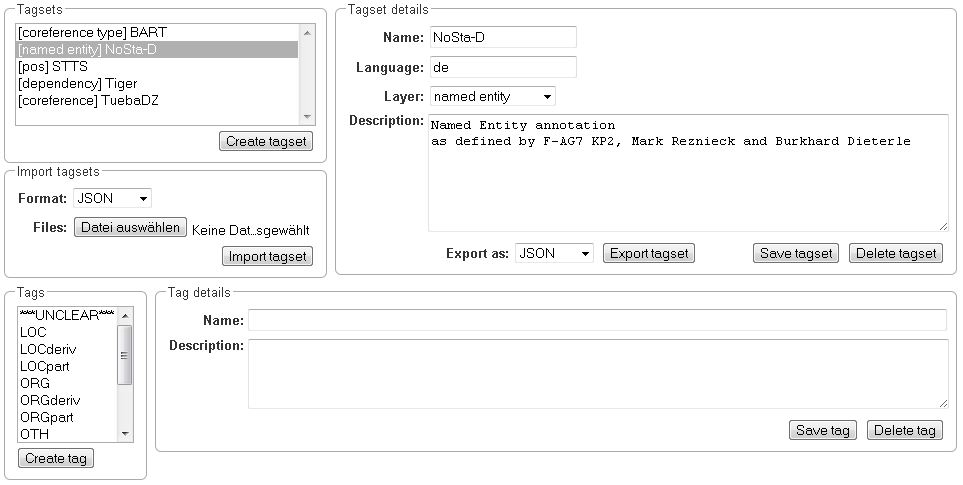
In the Frame Tagset details, you can change them, export a tagset, save the changes you made on it or delete it by clicking on Delete tagset. To change an individual tag, you select one in the list displayed in the frame Tags. You can then change its description or name or delete it by clicking Delete tag in Tag details. Please do not forget to save your changes by clicking on Save tag. To add a new tag, you have to click on Create tag in Tag details. Then you add the name and the description, which is optional. Again, do not forget to click Save tag or the new tag will not be created.
To create an own tagset, click on Create tagset and fill in the fields that will be displayed in the new frame. Only the first field is obligatory. Adding new tags works the same way as described for already existing tagsets. If you want to have a free annotation, as it could be used for lemma or meta information annotation, do not add any tags.
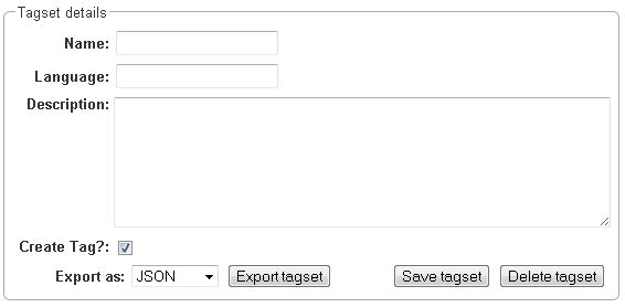
To export a tagset, choose the format of the export at the bottom of the frame and click Export tagset.
Export
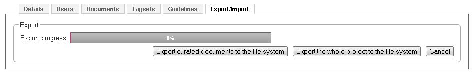
Two modes of exporting projects are supported:
-
Export the whole project for the purpose of creating a backup, of migrating it to a new WebAnno version, of migrating to a different WebAnno instance, or simply in order to re-import it as a duplicate copy.
-
Export curated documents for the purpose of getting an easy access to the final annotation results. If you do not have any curated documents in your project, this export option is not offered. A re-import of these archives is not possible.
A whole project export always serves as an archive which can be re-imported again since it includes the annotations in the format internally used by the application. In addition to the internal format, the annotations can be included in a secondary format in the export. This format is controlled by the Format drop-down field. When AUTO is selected, the file format corresponds to the format of the source document. If there is no write support for the source format, the file is exported in the WebAnno TSV3 format instead.
| The AUTO format export annotated files in the format of the originally imported file. If the original file format did not contain any annotations (e.g. plain text files) or only specific types of annotations (e.g. CoNLL files), the secondary annotation files will also have none or limited annotations. |
When exporting a whole project, the structure of the exported ZIP file is as follows:
-
<project ID>.json - project metadata file
-
annotation
-
<source document name>
-
<user ID>.XXX - file representing the annotations for this user in the selected format.
-
CORRECTION_USER.XXX - correction project: original document state, automation project automatically generated suggestions
-
-
-
annotation_ser
-
<source document name>
-
<user ID>.ser - serialized CAS file representing the annotations for this user
-
CORRECTION_USER.ser - correction project: original document state, automation project automatically generated suggestions
-
-
-
curation
-
<source document name>
-
CURATION_USER.XXX - file representing the state of curation in the selected format.
-
-
-
curation_ser
-
<source document name>
-
CURATION_USER.ser - serialized UIMA CAS representing the state of curation
-
-
-
log
-
<project ID>.log - project log file
-
-
source - folder containing the original source files
| Some browsers automatically extract ZIP files into a folder after the download. Zipping this folder and trying to re-import it into the application will generally not work because the process introduces an additional folder level within the archive. The best option is to disable the automatic extraction in your browser. E.g. in Safari, go to Preferences → General and disable the setting Open "safe" files after downloading. |
The files under annotation and curation are provided for convenience only. They are
ignored upon import.
|
The CORRECTION_USER.XXX and CURATION_USER.ser may be located in the curation and
curation_ser folders for old exported projects.
|
Currently, it is not possible to choose a specific format for bulk-exporting annotations. However, this mailing list post describes how DKPro Core can be used to transform the UIMA CAS formats into alternative formats.
User Management
| This functionality is only available to administrators. |
After selecting this functionality, a frame which shows all users is displayed. By selecting a user, a frame is displayed on the right.
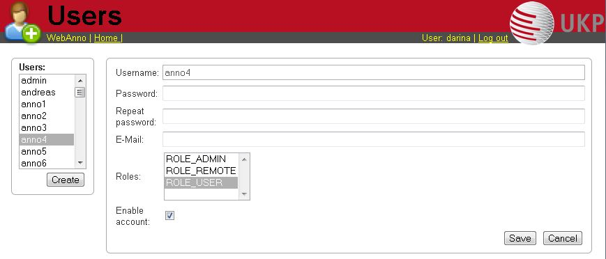
Now you may change his role or password, specify an e-mail address and dis- or enable his account by placing the tick.
| Disabling an account prevents the user from logging in. The user remains associated with any projects and remains visible in on the Monitoring page. |
To create a new user, click on Create in the left frame. This will display a similar frame as the one described in the last paragraph. Here you have to give a login-name to the new user.
In both cases, do not forget to save your changes by pressing the Save button.
-
User roles
Role |
Description |
ROLE_USER |
User. Required to log in to the application. Removal of this role from an account will prevent login even for users that additionally hold the ROLE_ADMIN! |
ROLE_ADMIN |
Administrator. Can manage users and has access to all other functionalities. |
ROLE_PROJECT_CREATOR |
Project creator. Can create new projects. |
ROLE_REMOTE |
Remote API access. Currently experimental and undocumented. Do not use. |
Advanced functionalities
Correction
| This functionality is only available to annotators and managers. |
In this page, already annotated documents may be checked, corrected and enhanced.
Before being able to see and correct documents, make sure to have chosen correction when creating your project in projects. For detailed instructions please refer to Projects. Also make sure that the documents you upload are already annotated.
After clicking on the Correction symbol on the main page, the Correction page is opened. In the appearing frame, which is the left one in the image below, the user has to choose a project first.
Afterwards the documents assigned to him are displayed. Now he may choose a document. Just like in Annotation and Curation, the color of the document names signals the following: black - unopened document, blue - opened document and red - document finished.
After having chosen the document, two frames are displayed.
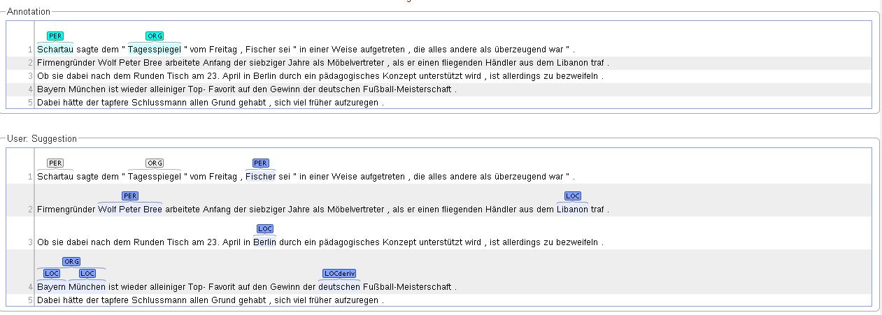
The upper one, Annotation, is the frame in which annotations can be made by the user. Moreover, it displays the chosen annotations. The lower frame, User: Suggestion, displays the annotation that was previously made in the uploaded document. By clicking on the annotations (not the words), they are chosen as right and are therefore displayed in the Annotation frame. Additional annotations may be made just like in Annotation, by selecting the span or relation to be annotated, choosing the layer and tag. For more detailed instruction or the guidelines for the navigation in the upper frames (Document, Page, Help, Workflow), see the guidelines for Annotation. No changes may be made in the lower frame.
The coloring of the annotation signals the same as in Curation.
Automation
| This functionality is only available to managers and administrators. |
This functionality gives the possibility to choose features and documents, which can be used for training of all layers that are offered in WebAnno (lemma, NER, POS and co-ref).
Setup
After clicking on Create Project on the Projects page, select automation as your project type. The detailed description may be found in Projects.
The documents, that are to be annotated, have to be uploaded in the frame Documents. Please make sure that the chosen format corresponds to the format of the files you are uploading.
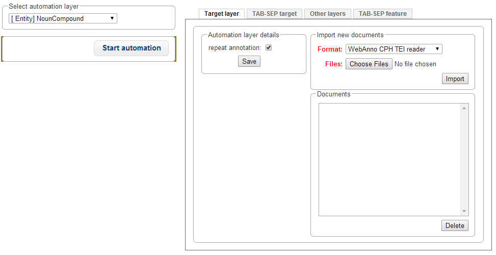
To manage the automation process, choose the Automation frame. The following frame will appear:
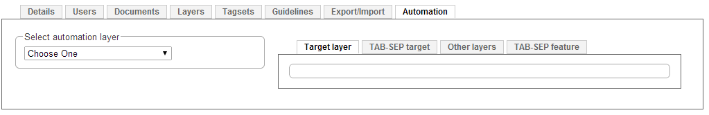
First choose your target layer in the Select automation layer frame. If you want to train a non-custom layer, please make sure you created or imported it in the Layer frame (for instructions to do so, see Projects).
Here you may choose the format of the target layer and optionally add some feature layers on which you want to train.
In the tab Target layer you may upload training files containing the target layer in WebAnno Export formats (WebAnno CPH TEI reader, plain text, binary format, XMI format, old WebAnno Format, WebAnno Format, Weblicht TCF Format, for more information on these formats, see [https://code.google.com/p/webanno/wiki/Format?ts=1407336468&updated=Format Format]).
In the next tab TAB-SEP target, you may upload training files containing the target layer in a tab-separated format, which is structured by writing each single word in a line together with its target tag, separated by a tab. Sentences are separated by blank lines.
The same goes analogically for the feature layers. The Other layers tab gives the possibility to upload WebAnno Export formats and choosing the layers that are to be used in training in the format window. The TAB-SEP feature tab gives the possibility to upload files in the above described tab-separated format, containing the feature tags in the second column. Every file will be regarded as one separate feature.
After choosing the training files, uploading them in the right format and importing them (by clicking on Import), every file will be displayed in the corresponding tab in the frame Documents. Click on the button Start Automation on the left, when you have uploaded your training data. Be prepared to wait for some time, as automation is a non-trivial process.
You can see that the automation has finished either by the fact that the Start Automation button is enabled again, or on the Monitoring page, by choosing the project in Monitoring and looking at the progress shown in the Training results /status frame.
Annotation
To see the tags that were automatically created during the previously described, go to Home and choose the Automation page. Then select a project and a file, analogically to Annotation. The page, which is demonstrated below will be displayed. The navigation, export and the marking of finished documents is the same as in Annotation.
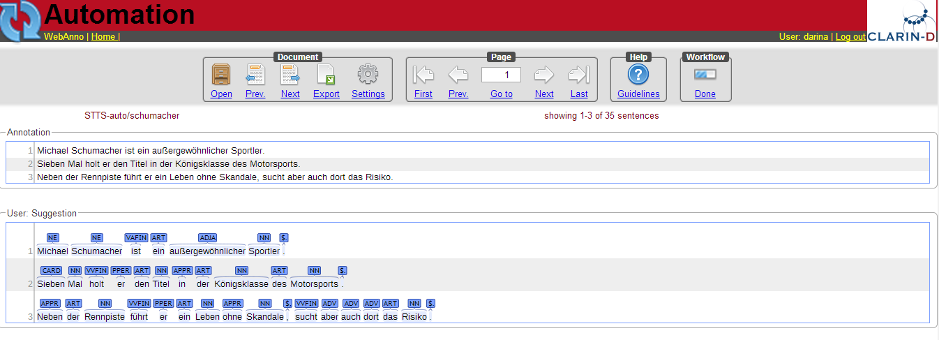
In the lower part, you see two horizontal frames, the lower one showing the automatically created annotation. By clicking on the tags, they are selected and therefore appear in the upper frame Annotation. You may see that selected tags turn grey in the Automation frame and blue in the Annotation frame. You may also add new tags to the Annotation, just like on the Annotation page.
Constraints
Constraints reorder the choice of tags based on the context of an annotation. For instance, for a given lemma, not all possible part-of-speech tags are sensible. Constraint rules can be set up to reorder the choice of part-of-speech tags such that the relevant tags are listed first. This speeds up the annotation process as the annotator can choose from the relevant tags more conveniently.
The choice of tags is not limited, only the order in which they are presented to the annotator. Thus, if the project manager has forgotten to set up a constraint or did possible not consider an oddball case, the annotator can still make a decision.
Importing constraints
To import a constraints file, go to Project and click on the particular project name. On the left side of the screen, a tab bar opens. Choose Constraints. You can now choose a constraint file by clicking on Choose Files. Then, click on Import. Upon import, the application checks if the constraints file is well formed. If they conform to the rules of writing constraints, the constraints are applied.
Implementing constraint sets
A constraint set consists of two components:
-
import statement
-
scopes
-
Import statements* are composed in the following way:
import <fully_qualified_name_of_layer> as <shortName>;It is necessary to declare short names for all fully qualified names because only short names can be used when writing a constraint rule. Short names cannot contain any dots or special characters, only letters, numbers, and the underscore.
| All identifiers used in constraint statements are case sensitive. |
| If you are not sure what the fully qualified name of a layer is, you can look it up going to Layers in Project settings. Click on a particular layer and you can view the fully qualified name under Technical Properties. |
Scopes consist of a scope name and one or more rules that refer to a particular annotation layer and define restrictions for particular conditions. For example, it is possible to reorder the applicable tags for a POS layer, based on what kind of word the annotator is focusing on.
While scope names can be freely chosen, scope rules have a fixed structure. They consist of conditions and restrictions, separated by an arrow symbol (→).
Conditions consist of a path and a value, separated by an equal sign (=). Values always have to be embraced by double-quotes. Multiple conditions in the same rule are connected via the &-operator, multiple restrictions in the same rule are connected via the |-operator.
Typically a rule’s syntax is
<scopeName> {
  <condition_set> -> <restriction_set>;
}
This leads to the following structure:
<scopeName> {
  <rule_1>;
  ...
  <rule_n>;
}
Both conditions and restrictions are composed of a path and a value. The latter is always enclosed in double quotes.
<path>="<value>"A condition is a way of defining whether a particular situation in WebAnno is based on annotation layers and features in it. Conditions can be defined on features with string, integer or boolean values, but in any case, the value needs to be put into quotes (e.g. someBooleanFeature="true", someIntegerFeature="2").
A condition set consists of one or more conditions. They are connected with logical AND as follows.
<condition> & <condition>A restriction set defines a set of restrictions which can be applied if a particular condition set is evaluated to true. As multiple restrictions inside one rule are interpreted as conjunctions, they are separated by the |-operator. Restrictions can only be defined on String-valued features that are associated with a tagset.
<restriction> | <restriction>A path is composed of one or more steps, separated by a dot. A step consists of a feature selector and a type selector.
Type selectors are only applicable while writing the condition part of a rule. They comprise a layer operator @ followed by the type (Lemma, POS, etc).
Feature selectors consist of a feature name, e.g.
pos.PosValueNavigation across layers is possible via
@<shortLayerName>Hereby all annotations of type <shortLayerName> at the same position as the current context are found.
Comments
The constraint language supports block comments which start with / and end with /. These
comments may span across multiple lines.
/* This is a single line comment */

/*
   This is a multi-
   line comment
*/
Conditional features
Constraints can be used to set up conditional features, that is features that only become available in the UI if another feature has a specific value. Let’s say that for example you want to annotate events and only causing events should additionally offer a polarity feature, while for caused events, there should be no way to select a polarity.
Sticking with the example of annotating events, conditional features can be set up as following:
-
Go to the Layer tab of the project settings
-
Create a new tagset called Event category and add the tags causing and caused
-
Create a new tagset called Event polarity and add the tags positive and negative
-
Create a new span layer called Event
-
Add a string feature called category and assign the tagset Event category
-
Save the changes to the category feature
-
Add a string feature called polarity and assign the tagset Event polarity
-
Enabled the checkbox Hide Un-constraint feature on the polarity feature
-
Save the changes to the polarity feature
-
Create a new text file called
constraints.txtwith the following contents .
import webanno.custom.Event as Event;

Event {
  category="causing" -> polarity="positive" | polarity="negative";
}
-
Import
constraints.txtin the tab Constraints in the project settings.
When you now annotate an Event in this project, then the polarity feature is only visible and editable if the category of the annotation is set to causing.
| It is important that both of the features have tagsets assigned - otherwise the conditional effect will not take place. |
Constraints for slot features
Constraints can be applied to the roles of slot features. This is useful, e.g. when annotating predicate/argument structures where specific predicates can only have certain arguments.
Consider having a span layer SemPred resembling a semantic predicate and bearing a slot feature arguments and a string feature senseId. We want to restrict the possible argument roles based on the lemma associated with the predicate. The first rule in the following example restricts the senseId depending on the value of a Lemma annotation at the same position as the SemPred annotation. The second rule then restricts the choice of roles for the arguments based on the senseId. Note that to apply a restriction to the role of a slot feature, it is
necessary to append .role to the feature name (that is because role is technically a nested feature).
Thus, while we can write e.g. senseId = "Request" for a simple string feature, it is necessary to write arguments.role = "Addressee".
Note that some role labels are marked with the flag (!). This is a special flag for slot features and indicates that slots with these role labels should be automatically displayed in the UI ready to be filled. This should be used for mandatory or common slots and saves time as the annotator does not have to manually create the slots before filling them.
SemPred {
  /* Rule 1 */
  @Lemma.value = "ask" -> senseId = "Questioning" | senseId = "Request" | senseId = "XXX";
  /* .. other lemmata */
  /* Rule 2 */
  senseId = "Questioning" ->
    /* core roles */
    arguments.role = "Addressee" (!) | arguments.role = "Message" (!) | arguments.role = "Speaker" (!) |
    /* non-core roles */
    arguments.role = "Time" | arguments.role = "Iterations";
  /* .. other senses */
}
Constraints language grammar
// Basic structure ---------------------------------------
<file>            ::= <import>* | <scope>*
<scope>           ::= <shortLayerName> "{" <ruleset> "}"
<ruleset>         ::= <rule>*
<import>          ::= "import" <qualifiedLayerName>
                      "as" <shortLayerName>
<rule>            ::= <conds> "->" <restrictions> ";"

// Conditions --------------------------------------------
<conds>           ::= <cond> | <cond> "&" <conds>
<cond>            ::= <path> "=" <value>
<path>            ::= <featureName> | <step> "." <path>
<step>            ::= <featureName> | <layerSelector>
<layerSelector>   ::= <layerOperator>? <shortLayerName>
<layerOperator>   ::= "@" // select annotation in layer X

// Restrictions ------------------------------------------
<restrictions>    ::= <restriction> |
                      <restriction> "|" <restrictions>
<restriction>     ::= <restrictionPath> "=" <value>
                      ( "(" <flags> ")" )
<restrictionPath> ::= <featureName> |
                      <restrictionPath> "." <featureName>
<flags>           ::= "!" // core role
CAS Doctor
The CAS Doctor is an essential development tool. When enabled, it checks the CAS for consistency when loading or saving a CAS. It can also automatically repair inconsistencies when configured to do so. This section gives an overview of the available checks and repairs.
It is safe to enable any checks. However, active checks may considerably slow down the application, in particular for large documents or for actions that work with many documents, e.g. curation or the calculation of agreement. Thus, checks should not be enabled on a production system unless the application behaves strangely and it is necessary to check the documents for consistency.
Enabling repairs should be done with great care as most repairs are performing
destructive actions. Repairs should never be enabled on a production system. The repairs are
executed in the order in which they are appear in the debug.casDoctor.repairs setting. This is
important in particular when applying destructive repairs.
When documents are loaded, CAS Doctor first tries to apply any enabled repairs and afterwards applies enabled checks to ensure that the potentially repaired document is consistent.
Additionally, CAS Doctor applies enabled checks before saving a document. This ensures that a bug in the user interface introduces inconsistencies into the document on disk. I.e. the consistency of the persisted document is protected! Of course, it requires that relevant checks have been implemented and are actually enabled.
By default, CAS Doctor generates an exception when a check or repair fails. This ensures that inconsistencies are contained and do not propagate further. In some cases, e.g. when it is known that by its nature an inconsistency does not propagate and can be avoided by the user, it may be convenient to allow the user to continue working with the application while a repair is being developed. In such a case, CAS Doctor can be configured to be non-fatal. Mind that users can always continue to work on documents that are consistent. CAS Doctor only prevents loading inconsistent documents and saving inconsistent documents.
Configuration
| Setting | Description | Default | Example |
|---|---|---|---|
debug.casDoctor.fatal |
If the extra checks trigger an exception |
true |
false |
debug.casDoctor.checks |
Extra checks to perform when a CAS is saved (also on load if any repairs are enabled) |
unset |
comma-separated list of checks |
debug.casDoctor.repairs |
Repairs to be performed when a CAS is loaded - order matters! |
unset |
comma-separated list of repairs |
debug.casDoctor.forceReleaseBehavior |
Behave as like a release version even if it is a beta or snapshot version. |
false |
true |
Checks
All feature structures indexed
| ID |
|
| Related repairs |
Remove dangling chain links, Remove dangling relations, Re-index feature-attached spans, Remove dangling feature-attached span annotations |
This check verifies if all reachable feature structures in the CAS are also indexed. We do not currently use any un-indexed feature structures. If there are any un-indexed feature structures in the CAS, it is likely due to a bug in the application and can cause undefined behavior.
For example, older versions of WebAnno had a bug that caused deleted spans still to be accessible through relations which had used the span as a source or target.
This check is very extensive and slow.
Feature-attached spans truly attached
| ID |
|
| Related repairs |
Re-attach feature-attached spans, Re-attach feature-attached spans and delete extras |
Certain span layers are attached to another span layer through a feature reference
from that second layer. For example, annotations in the POS layer must always be referenced from
a Token annotation via the Token feature pos. This check ensures that annotations on layers such
as the POS layer are properly referenced from the attaching layer (e.g. the Token layer).
Links reachable through chains
| ID |
|
| Related repairs |
Each chain in a chain layers consist of a chain and several links. The chain points to the first link and each link points to the following link. If the CAS contains any links that are not reachable through a chain, then this is likely due to a bug.
No multiple incoming relations
| ID |
|
Check that nodes have only one in-going dependency relation inside the same annotation layer. Since dependency relations form a tree, every node of this tree can only have at most one parent node. This check outputs a message that includes the sentence number (useful to jump directly to the problem) and the actual offending dependency edges.
No 0-sized tokens and sentences
| ID |
|
| Related repairs |
Zero-sized tokens and sentences are not valid and can cause undefined behavior.
Relation offsets consistency
| ID |
|
| Related repairs |
Checks that the offsets of relations match the target of the relation. This mirrors the DKPro Core convention that the offsets of a dependency relation must match the offsets of the dependent.
Repairs
Re-attach feature-attached spans
| ID |
|
This repair action attempts to attach spans that should be attached to another span, but are not.
E.g. it tries to set the pos feature of tokens to the POS annotation for that respective token.
The action is not performed if there are multiple stacked annotations to choose from. Stacked
attached annotations would be an indication of a bug because attached layers are not allowed to
stack.
This is a safe repair action as it does not delete anything.
Re-attach feature-attached spans and delete extras
| ID |
|
This is a destructive variant of Re-attach feature-attached spans. In addition to re-attaching unattached annotations, it also removes all extra candidates that cannot be attached. For example, if there are two unattached Lemma annotations at the position of a Token annotation, then one will be attached and the other will be deleted. Which one is attached and which one is deleted is undefined.
Re-index feature-attached spans
| ID |
|
This repair locates annotations that are reachable via a attach feature but which are not actually indexed in the CAS. Such annotations are then added back to the CAS indexes.
This is a safe repair action as it does not delete anything.
Repair relation offsets
| ID |
|
Fixes that the offsets of relations match the target of the relation. This mirrors the DKPro Core convention that the offsets of a dependency relation must match the offsets of the dependent.
Remove dangling chain links
| ID |
|
This repair action removes all chain links that are not reachable through a chain.
Although this is a destructive repair action, it is likely a safe action in most cases. Users are not able see chain links that are not part of a chain in the user interface anyway.
Remove dangling feature-attached span annotations
| ID |
|
This repair action removes all annotations which are themselves no longer indexed (i.e. they have been deleted), but they are still reachable through some layer to which they had attached. This affects mainly the DKPro Core POS and Lemma layers.
Although this is a destructive repair action, it is sometimes a desired action because the user may know that they do not care to resurrect the deleted annotation as per Re-index feature-attached spans.
Remove dangling relations
| ID |
|
This repair action removes all relations that point to unindexed spans.
Although this is a destructive repair action, it is likely a safe action in most cases. When deleting a span, normally any attached relations are also deleted (unless there is a bug). Dangling relations are not visible in the user interface.
Remove 0-size tokens and sentences
| ID |
|
This is a destructive repair action and should be used with care. When tokens are removed, also any attached lemma, POS, or stem annotations are removed. However, no relations that attach to lemma, POS, or stem are removed, thus this action could theoretically leave dangling relations behind. Thus, the Remove dangling relations repair action should be configured after this repair action in the settings file.
Upgrade CAS
| ID |
|
Ensures that the CAS is up-to-date with the project type system. It performs the same operation which is regularly performed when a user opens a document for annotation/curation.
This is considered to be safe repair action as it only garbage-collects data from the CAS that is no longer reachable anyway.
Annotation Guidelines
Providing your annotation team with guidelines helps assuring that every team member knows exactly what is expected of them.
Annotators can access the guidelines via the Guidelines button on the annotation page.
Project managers can provide these guidelines via the Guidelines tab in the project settings. Guidelines are provided as files (e.g. PDF files). To upload guidelines, click on Choose files, select a file from your local disc and then click Import guidelines. Remove a guideline document by selecting it and pressing the Delete button.
Appendices
WebAnno TSV 3.2 File format
In this section, we will discuss the WebAnno TSV (Tab Separated Value) file format version 3.2. The format is similar to the CoNNL file formats with specialized additions to the header and column representations. The file format inhabits a header and a body section. The header section present information about the different types of annotation layers and features used in the file. While importing the WebAnno TSV file, the specified headers should be first created in to the running WebAnno project. Otherwise, the importing of the file will not be possible.
The body section of the TSV file presents the document and all the associated annotations including sentence and token annotations.
Encoding and Offsets
TSV files are always encoded in UTF-8. However, the offsets used in the TSV file are based on UTF-16. This is important when using TSV files with texts containing e.g. Emojis or some modern non-latin Asian, Middle-eastern and African scripts.
WebAnno is implemented in Java. The Java platform internally uses a UTF-16 representation for text. For this reason, the offsets used in the TSV format currently represent offsets of the 16bit units in UTF-16 strings. This is important if your text contains Unicode characters that cannot be represented in 16bit and which thus require two 16bit units. For example a token represented by the Unicode character 😊 (U+1F60A) requires two 16bit units. Hence, the offset count increased by 2 for this character. So Unicode characters starting at U+10000 increase the offset count by 2.
#Text=I like it 😊 .
1-1 0-1 I _
1-2 2-6 like  _
1-3 7-9 it  _
1-4 10-12 😊  *
1-5 13-14 . _| Since the character offsets are based on UTF-16 and the TSV file itself is encoded in UTF-8, first the text contained in the file needs to be transcoded from UTF-8 into UTF-16 before the offsets can be applied. The offsets cannot be used for random access to characters directly in the TSV file. |
File Header
WebAnno TSV 3.2 file starts with the following header marker
#FORMAT=WebAnno TSV 3.2Layers are marked by the # character followed by T_SP= for span types (including slot features), T_CH= for chain layers, and T_RL= for relation layers. Every layer is written in new line, followed by the features in the layer.
If all layer type exists, first, all the span layers will be written, then the chain layer, and finally the relation layers.
Features are separated by the | character and only the short name of the feature is provided.
#T_SP=webanno.custom.Pred|bestSense|lemmaMapped|senseId|senseMappedHere the layer name is webanno.custom.Pred and the features are named bestSense, lemmaMapped, senseId, senseMapped.
Slot features start with a prefix ROLE_ followed by the name of the role and the link. The role feature name and the link feature name are separated by the _ character.
The target of the slot feature always follows the role/link name
#T_SP=webanno.custom.SemPred|ROLE_webanno.custom.SemPred:RoleSet_webanno.custom.SemPredRoleSetLink|uima.tcas.Annotation|aFrameHere the name of the role is webanno.custom.SemPred:RoleSet and the name of the role link is webanno.custom.SemPredRoleSetLink and the target type is uima.tcas.Annotation.
Chain layers will have always two features, referenceType and referenceRelation.
#T_CH=de.tudarmstadt.ukp.dkpro.core.api.coref.type.CoreferenceLink|referenceType|referenceRelationRelation layers will come at last in the list and the very last entry in the features will be the type of the base (governor or dependent) annotations with a prefix BT_.
#T_RL=de.tudarmstadt.ukp.dkpro.core.api.syntax.type.dependency.Dependency|DependencyType|BT_de.tudarmstadt.ukp.dkpro.core.api.lexmorph.type.pos.POSHere, the relation type de.tudarmstadt.ukp.dkpro.core.api.syntax.type.dependency.Dependency has a feature DependencyType and the relation is between a base type of de.tudarmstadt.ukp.dkpro.core.api.lexmorph.type.pos.POS.
File Body / Annotations
In this section we discuss the different representations of texts and annotation in WebAnno TSV3format
Reserved Characters
Reserved characters have a special meaning in the TSV format and must be are escaped with the backslash (\) character if they appear in text or feature values. Reserved characters are the following:
\,[,],|,_,->,;,\t,\n,*
The way that TSV is presently defined/implemented, it kind of considers → as a single
"character"… and it is also escaped as a single unit, i.e. → becomes ->. It is something to
be addressed in a future iteration of the format.
|
Sentence Representation
Sentence annotations are presented following the text marker #Text=, before the token
annotations. All text given here is inside the sentence boundaries.
#Text=Bell , based in Los Angeles , makes and distributes electronic , computer and building products .The text of an imported document is reconstructed from the sentence annotations. Additionally, the offset information of the sentence tokens are taken into account to determine whether padding needs to be added between sentences. The TSV format can presently not record text that occurs in between two sentences.
If a sentence spans multiple lines, the text is split at the line feed characters (ASCII 12) and
multiple #Text= lines are generated. Note that carriage return characters (ASCII 13) are kept
as escaped characters (\r).
#Text=Bell , based in Los Angeles , makes and distributes
#Text=electronic , computer and building products .
Token and Sub-token Annotations
Tokens represent a span of text within a sentence. Tokens cannot overlap, although then can be directly adjacent (i.e. without any whitespace between them). The start offset of the first character of the first token corresponds to the start of offset of the sentence.
Token annotation starts with a sentence-token number marker followed by the begin-end offsets
and the token itself, separated by a TAB characters.
1-2 4-8 HaagHere 1 indicates the sentence number, 2 indicates the token number (here, the second token
in the first sentence) and 4 is the begin offset of the token and 8 is the end offset of the
token while Haag is the token.
Sub-token representations are affixed with a . and a number starts from 1 to N.
1-3        9-14        plays
1-3.1        9-13        play
1-3.2        13-14        s
Here, the sub-token play is indicated by sentence-token number 1-3.1 and the sub-token s is
indicated by 1-3.2.
While tokens may not overlap, sub-tokens may overlap.
1-3 9-14  plays
1-3.1 9-12  pla
1-3.2 11-14 ays
Span Annotations
For every features of a span Annotation, annotation value will be presented in the same row as the token/sub-token annotation, separated by a TAB character. If there is no annotation for the given span layer, a _ character is placed in the column. If the feature has no/null annotation or if the span layer do not have a feature at all, a * character represents the annotation.
#T_SP=de.tudarmstadt.ukp.dkpro.core.api.lexmorph.type.pos.POS|PosValue
#T_SP=webanno.custom.Sentiment|Category|Opinion1-9 36-43 unhappy JJ abstract negativeHere, the first annotation at column 4, JJ is avalue for a feature PosValue of the layer de.tudarmstadt.ukp.dkpro.core.api.lexmorph.type.pos.POS. For the two features of the layer webanno.custom.Sentiment (Category and Opinion), the values abstract and negative are
presented at column 5 and 6 resp.
When serializing a span annotation starts or ends in a space between tokens, then the
annotation is truncated to start at the next token after the space or to end at the last token
before the space. For example, if you consider the text [one two] and there is an some span annotation
on [one ] (note the trailing space), the extent of this span annotation will be serialized as only
covering [one]. It is not possible in this format to have annotations starting or ending in
the space between tokens because the inter-token space is not rendered as a row and therefore is not
addressable in the format.
|
Disambiguation IDs
Within a single line, an annotation can be uniquely identified by its type and stacking index. However, across lines, annotation cannot be uniquely identified easily. Also, if the exact type of the referenced annotation is not known, an annotation cannot be uniquely identified. For this reason, disambiguation IDs are introduced in potentially problematic cases:
-
stacked annotations - if multiple annotations of the same type appear in the same line
-
multi-unit annotations - if an annotations spans multiple tokens or sub-tokens
-
un-typed slots - if a slot feature has the type
uima.tcas.Annotationand may thus refer to any kind of target annotation.
The disambiguation ID is attached as a suffix [N] to the annotation value. Stacked annotations are separated by | character.
#T_SP=de.tudarmstadt.ukp.dkpro.core.api.lexmorph.type.pos.POS|PosValue
#T_SP=de.tudarmstadt.ukp.dkpro.core.api.ner.type.NamedEntity|value1-1 0-3 Ms. NNP PER[1]|PERpart[2]
1-2 4-8 Haag NNP PER[1]Here, PER[1] indicates that token 1-1 and 1-2 have the same annotation (multi-token annotations) while PERpart[2] is the second (stacked) annotation on token 1-1 separated by | character.
| On chain layers, the number in brackets is not a disambiguation ID but rather a chain ID! |
Slot features
Slot features and the target annotations are separated by TAB character (first the feature column then the target column follows). In the target column, the sentence-token id is recorded where the feature is drawn.
Unlike other span layer features (which are separated by | character), multiple annotations for a slot feature are separated by the ; character.
#T_SP=webanno.custom.Frame|FE|ROLE_webanno.custom.Frame:Roles_webanno.custom.FrameRolesLink|webanno.custom.Lu
#T_SP=webanno.custom.Lu|luvalue2-1 27-30 Bob _ _ _ bob
2-2 31-40 auctioned transaction seller;goods;buyer 2-1;2-3[4];2-6
2-3 41-44 the _ _ _ clock[4]
2-4 45-50 clock _ _ _ clock[4]
2-5 52-54 to _ _ _ _
2-6 55-59 John _ _ _ john
2-7 59-60 . _ _ _ _Here, for example, at token 2-2, we have three slot annotations for feature Roles that are seller, goods, and buyer. The targets are on token 2-1 `, `2-3[4], and 2-6 respectively which are on annotations of the layer webanno.custom.Lu which are bob, clock and john.
Chain Annotations
In the Chain annotation, two columns (TAB separated) are used to represent the referenceType and the referenceRelation. A chain ID is attached to the referenceType to distinguish to which of the chains the annotation belongs. The referenceRelation of the chain is represented by the relation value followed by → and followed by the CH-LINK number where CH is the chain number and LINK is the link number (the order the chain).
#T_CH=de.tudarmstadt.ukp.dkpro.core.api.coref.type.CoreferenceLink|referenceType|referenceRelation1-1 0-2 He pr[1] coref->1-1
1-2 3-7 shot _ _
1-3 8-15 himself pr[1] coref->1-2
1-4 16-20 with _ _
1-5 21-24 his pr[1] *->1-3
1-6 25-33 revolver _ _
1-7 33-34 . _ _In this example, token 1-3 is marked as pr[1] which indicates that the referenceType is pr and it is part of the chain with the ID 1. The relation label is coref and with the CH-LINK number 1-2 which means that it belongs to chain 1 and this is the second link in the chain.
Relation Annotations
Relation annotations comes to the last columns of the TSV file format. Just like the span annotations, every feature of the relation layers are represented in a separate TAB. Besides, one extra column (after all feature values) is used to write the token id from which token/sub-token this arc of a relation annotation is drawn.
#T_SP=de.tudarmstadt.ukp.dkpro.core.api.lexmorph.type.pos.POS|PosValue
#T_RL=de.tudarmstadt.ukp.dkpro.core.api.syntax.type.dependency.Dependency|DependencyType|BT_de.tudarmstadt.ukp.dkpro.core.api.lexmorph.type.pos.POS1-1 0-3 Ms. NNP SUBJ 1-3
1-2 4-8 Haag NNP SBJ 1-3
1-3 9-14 plays VBD P|ROOT 1-5|1-3
1-4 15-22 Elianti NNP OBJ 1-3
1-5 23-24 . . _ _In this example (say token 1-1), column 4 (NNP) is a value for the feature PosValue of the de.tudarmstadt.ukp.dkpro.core.api.lexmorph.type.pos.POS layer. Column 5 (SUBJ) records the value for the feature DependencyType of the de.tudarmstadt.ukp.dkpro.core.api.syntax.type.dependency.Dependency relation layer, where as column 6 (1-3) shows from which governor (VBD) the dependency arc is drawn.
For relations, a single disambiguation ID is not sufficient. If a relation is ambiguous, then
the source ID of the relation is followed by the source and target disambiguation ID separated
by an underscore (_). If only one of the relation endpoints is ambiguous, then the other one
appears with the ID 0. E.g. in the example below, the annotation on token 1-5 is ambiguous,
but the annotation on token 1-1 is not.
#FORMAT=WebAnno TSV 3.2
#T_SP=de.tudarmstadt.ukp.dkpro.core.api.ner.type.NamedEntity|value
#T_RL=webanno.custom.Relation|value|BT_de.tudarmstadt.ukp.dkpro.core.api.ner.type.NamedEntity


#Text=This is a test .
1-1 0-4 This  * _ _
1-2 5-7 is  _ _ _
1-3 8-9 a _ _ _
1-4 10-14 test  _ _ _
1-5 15-16 . *[1]|*[2] * 1-1[0_1]
Formats
| Format | Read | Write | Custom Layers | Description |
|---|---|---|---|---|
yes |
yes |
no |
POS, chunks |
|
yes |
yes |
no |
Named entities |
|
yes |
yes |
no |
Lemma, POS, dependencies (basic) |
|
yes |
yes |
no |
Lemma, POS, dependencies (basic) |
|
yes |
yes |
no |
Lemma, POS, dependencies (basic & enhanced), surface form |
|
Plain text |
yes |
yes |
no |
No annotations |
yes |
no |
no |
Lemma, POS, dependencies (basic), coreference, named entities |
|
TEI CPH dialect |
yes |
no |
no |
|
WebAnno TSV 1 |
yes |
no |
no |
|
WebAnno TSV 2 |
yes |
no |
yes |
token, multiple token, and arc annotations supported. No chain annotation is supported. no sub-token annotation is supported |
yes |
yes |
yes |
||
yes |
yes |
yes |
UIMA Binary CAS |
|
yes |
yes |
yes |
UIMA XMI CAS |
Troubleshooting
If the tool is kept open in the browser, but not used for a long period of time, you will have to log in again. For this, press the reload button of your browser.
If the tool does not react for more than 1 minute, please also reload and re-login.
We are collecting error reports to improve the tool. For this, the error must be reproducible: If you find a way how to produce the error, please open an issue and describe it.